Description
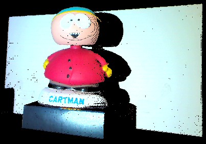
The software presented here can be used to scan 3D objects using a data projector and camera. This is an update to the original projector-calibration software which adds projection and capture of gray code patterns, together with pointcloud reconstruction functionalities.
Requirements
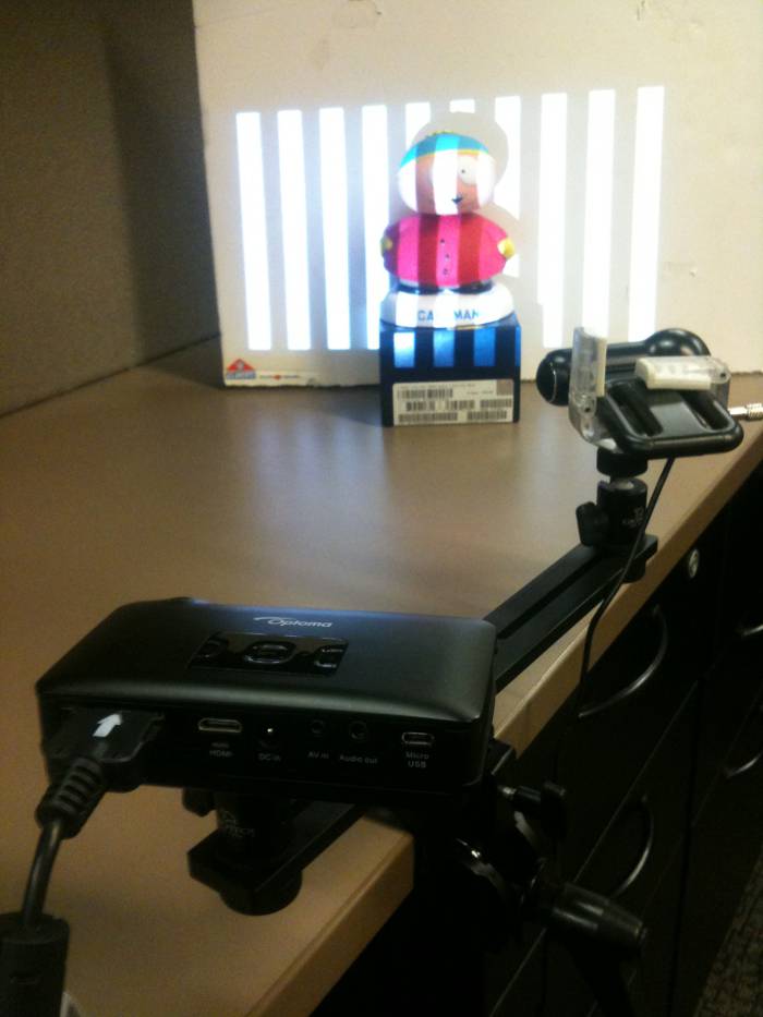
Software is tested in Microsoft Windows 7 and Apple OS X Mountain Lion. A typical configuration is to use an Optoma PK301 Pico Pocket Projector and Logitech QuickCam Pro 9000 webcam. For improved precision use a projector and camera with higher resolution. The capture module in the software should work with most USB webcams but if your camera is not supported, images can be captured using an external tool, and later read from a folder.
Data capture
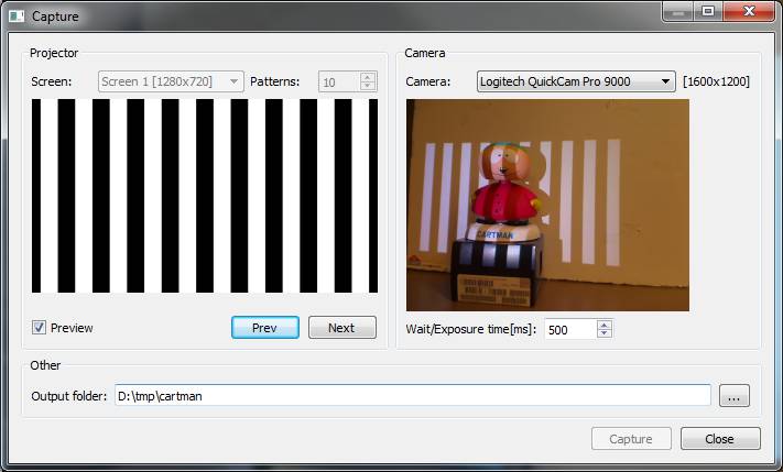
Make sure your data projector and camera are connected and click the "Capture..." button in the main window to open the dialog for data capture. Select the desired camera and the projector screen using the combo boxes on top and wait until the live view is shown. Enable the projector preview and change patterns to adjust the system prior capture.
Adjusting the system
Improved results are obtained if a moment is taken to adjust the components properly following these simple directions:
- Disable all auto-features from your camera. Auto focus, auto exposure, and other automatic parameters must be disabled prior to capture. How to disable camera features varies from camera to camera and cannot be done within the scanning software. If you are using the suggested Logitech camera you should download and install the manufacturer drivers in order to access the parameters on Microsoft Windows. On Apple OS X some parameters can be adjusted using UVC Camera Control.
- Adjust projector and camera orientation to maximize pixel usage. Place the target object at the desired location and move your camera and projector in such a way that the target covers a large area in the camera image and projected image.
- Adjust camera exposure (and possibly other parameters) to get a clear image. Use the projector and camera preview to see how captured images will look like and adjust the available camera parameters to get a clear image.
- Adjust projector and camera focus manually. If your projector and/or camera has a focus setting adjust it to improve the image quality. It is a good idea to use the projector preview buttons to project a pattern with several bars and look that the edges are sharp on the object surface.
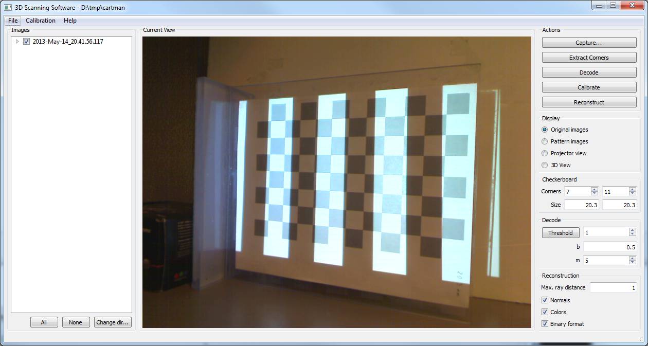
Once the system is properly adjusted, remove the target object and place a planar checkerboard pattern in its place. The size of the checkerboard must be similar to the target object size for better results. A black and white checkerboard pattern will usually work but in the case of the Optoma Pico projector a gray and white pattern worked better. Prefer non-symmetric patterns (e.g. a 6x8 checkerboard). Make sure that the complete checkerboard region is illuminated by the projector and seen in the camera image. Select on output directory in the dialog and press the "Capture" button (projector preview must be disabled at this point). A sequence of 42 images will be automatically projected and captured.
Repeat the procedure several times changing the checkerboard pose to cover the working volume as best as possible.
Calibration
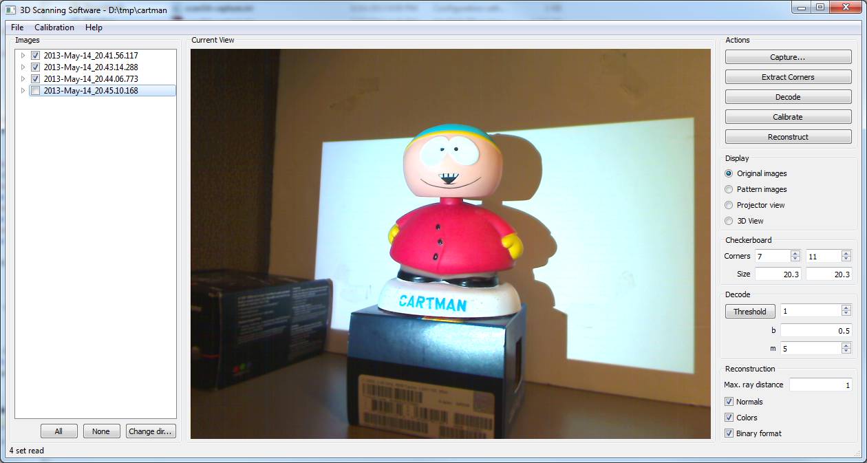
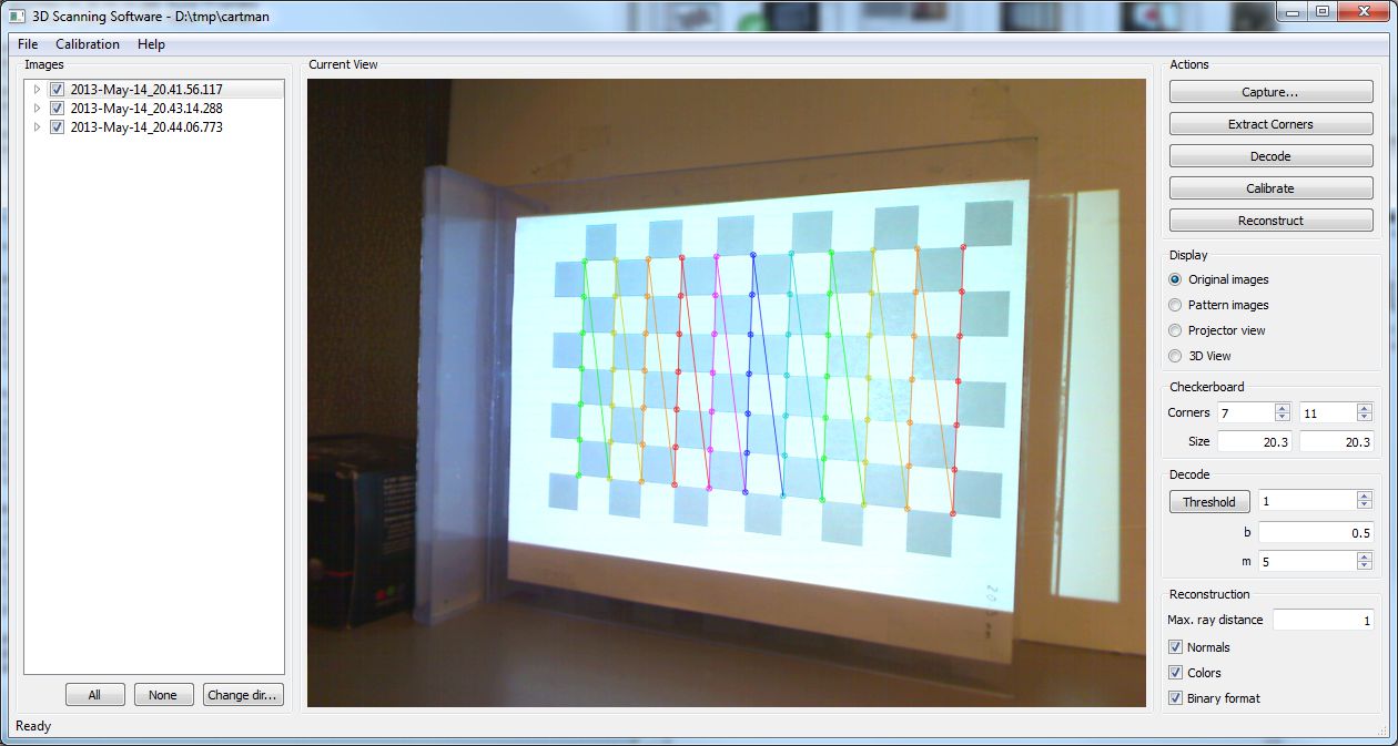
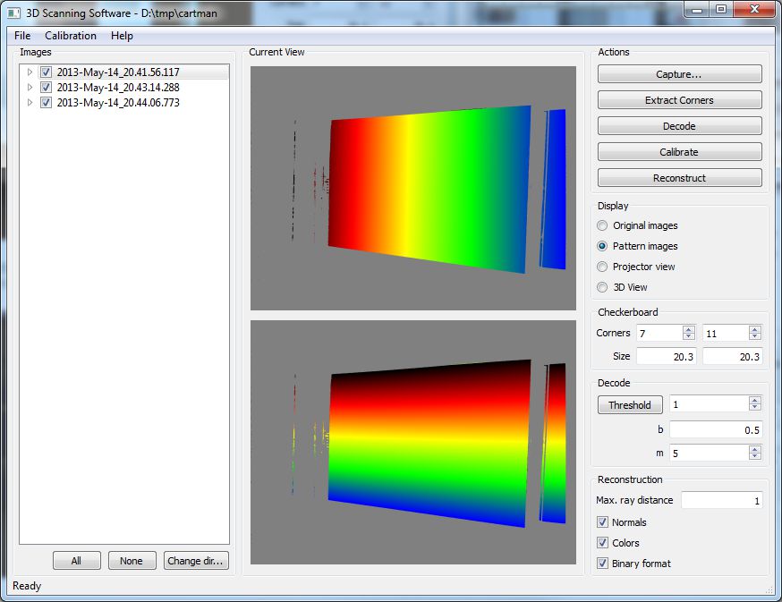
In the main window, fill the text boxes on the right with the number of interior corners of your checkerboard and its dimensions (e.g. millimeters, inches), and press "Calibrate" button. The software will automatically detect checkerboard corners, decode projected patterns, and calibrate both projector and camera. If any of the steps fails an error message will be shown and calibration will abort. Buttons "Extract Corners" and "Decode" can be used to execute and visualize individual steps. Optionally, some of the image sets may be disabled by unchecking them on the image list. By changing the view to "Pattern images" the decoded images can be visualized. The default parameters in the "Decode" group box works well in many cases but feel free to adjust them if you see errors in the decoded images.
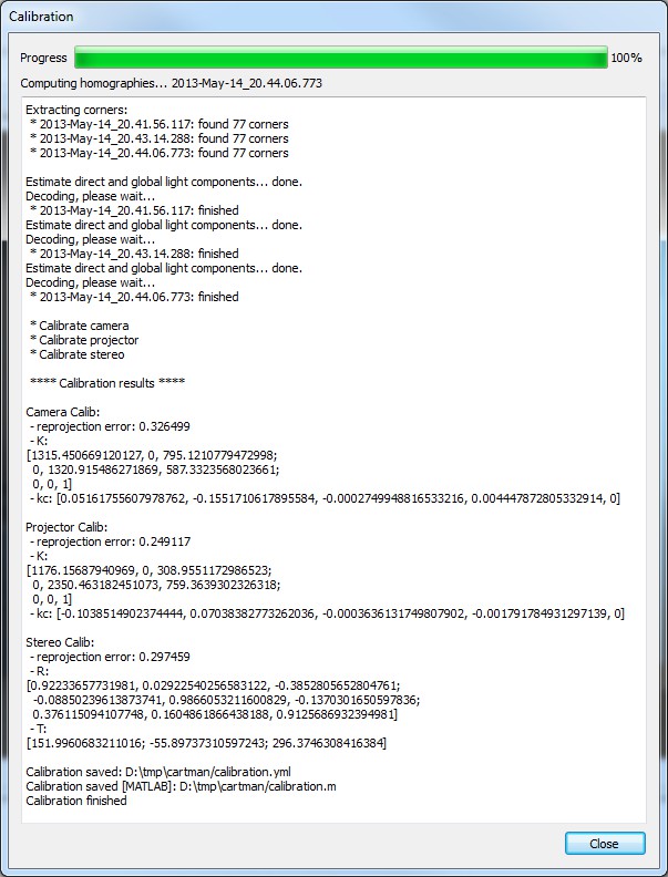
After a successful calibration, the output will show both the projector and camera reprojection errors. In a typical case, reprojection errors are between 0.1 and 0.5 pixels. If the result display a large reprojection error consider readjusting the system, capturing additional checkerboard poses, and/or disabling some of the captured checkerboard poses.
Model Scanning
Remove the checkerboard and place the target object in the working volume. Without changing anything in the physical setup or software configuration of projector and camera. Open the capture dialog again and capture a set of images of the target model. The same or different output folder can be used.
Return to the main window, highlight the captured image set by clicking on it on the left image set list, and press "Reconstruct" button on the right. A pointcloud of the model will be created and saved to a PLY file.
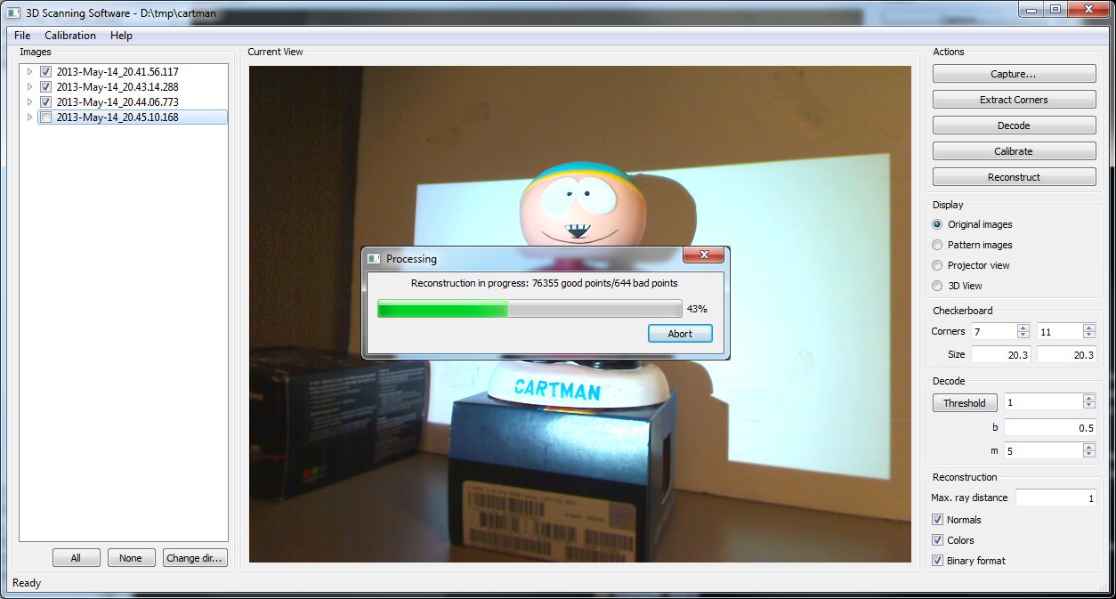
Repeat the procedure to capture additional views of the same model, or a different model.
At this point, an external tool (e.g. MeshLab) must be used to visualize, register, and merge pointclouds created with this method.