
Assignment 2: Iso-Curves and Iso-Surfaces
References
- The j3DPGP Application for this assignment,
j3DPGP-A2.zip, j3DPGP-public.zip, some data: tms.zip
Introduction
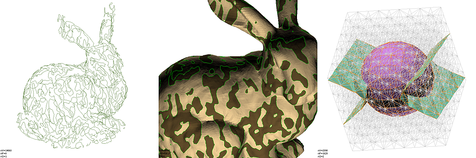
In this assignment you will implement a number of algorithms to compute polygonal approximations of implicit curves and surfaces. We will first focus on computing iso-curves for piece-wise linear functions specified by their values on the vertices of a triangle mesh. These are polygonal curves. Then we will implement an iso-surface extraction algorithm for tetrahedral meshes which produces polygon meshes.
1 Iso-Curves on Triangle Meshes
All these algorithms start with the common step of computing the isocurve vertices. Assuming linear interpolation along mesh edges, and that the isovalue is not attained by the function at mesh vertices, each isocurve vertex is located along one mesh edge, and no more than one vertex is supported by each edge. For each edge e=(i,j) of the mesh, with index iE, an isocurve vertex is supported on e if and only if the function changes sign along the edge, i.e., if the sign of the function at the two vertices of the edge have different signs with respect to the isovalue. The mapping from edge indices to isovertex indices can be stored in an auxiliary array of length equal to the total number of edges of the mesh. For consistency, a -1 vertex index can be used to indicate that an edge has not isovertex associated with.
As in the previous assignment, you should add your implementation to the J3DPanelIsoCurves.java file and recompile. A user interface is provided, as well as the skeletons of functions that you have to implement. Feel free to change both.
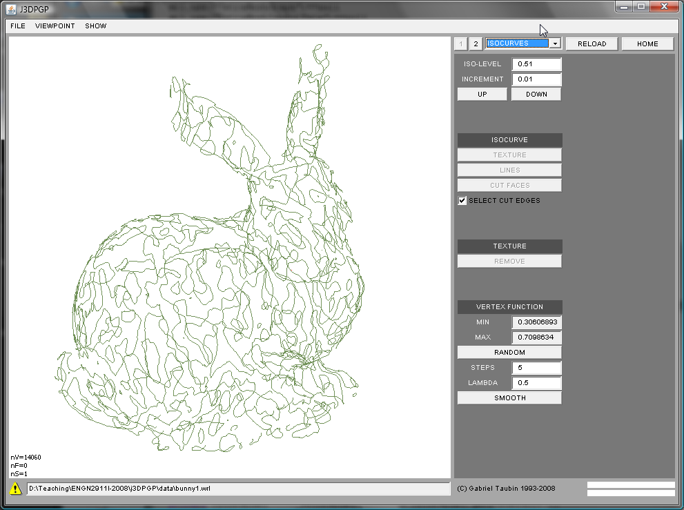
1.1 Extracting an Iso-Curve as an IndexedLineSet
Here the iso-curve will be stored in an WrlIndexedLineSet node, which will replace the WrlIndexedfaceSet. This is the definition of an IndexedLineSet node in the VRML'97 standard. You can find details about the meaning of the various fields in the WrlIndexedLineSetPublic.java file
IndexedLineSet {
  SFNode  color             NULL
  MFInt32 colorIndex        []     # [-1,INF)
  SFBool  colorPerVertex    TRUE
  SFNode  coord             NULL
  MFInt32 coordIndex        []     # [-1,INF)
}
The isovertex coordinates should be stored in the coord array of the WrlIndexedLineSet node. The isocurve edges should be stored in the coordIndex array as polylines. Within each triangle cut by the isocurve, the isocurve reduces to a line segment connecting two isocurve vertices. And the sign of the implicit function can be used to consistently orient these segments. For example, in the following picture
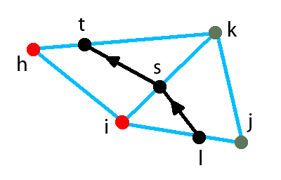
the two oriented isocurve segments (l,s) and (s,t) can be stored in the coordIndex array as separate unit length polylines:
coordIndex = [ ... -1 l s -1 s t -1 ... ]
or as a single polyline of length two:
coordIndex = [ ... -1 l s t -1 ... ]
If the mesh is manifold, has no boundaries, and the isolevel is not one of the values the function attains at a mesh vertex, then the isocurve is composed of a number of closed loops. The most efficient use of storage in the IndexedLineSet results from linking all the isoline edges. You need an additinal data structure to do the linking. The use of colors is optional. For example, you may want to paint each polyline with a different color.
1.2 Splitting triangular faces through and iso-curve
In the previous problem the constructed WrlIndexedLineSet replaces the WrlIndexFaceSet which contained the triangle mesh. In this problem we want to split faces of the triangle mesh in place. In this case the isovertices have to be assigned vertex indices consecutive to those of the input triangle mesh, and the new vertex coordinates have to be stored in the mesh coord array, following those of the input mesh. Other than that, the process of isovertex construction is the same as for the previous problem. We can follow the same approch as in the previous assignment: we traverse the input data structure and we generate output arrays. In this case we can avoid generating a separate coord array, but we need to generate a new coordIndex array which we will fill as we traverse the input coordArry. Faces not cut by the isocurve can be copied without modification. Each face cut by the isocurve will be replaced by a triangular face and a quadrilateral face (which can optionally be split into two triangles). For example, the input triangle (i,j,k) of the figure shown above, produces (i,l,s) and (l,j,k,s). which are consistently oriented with input faces, resulting in a properly oriented output mesh. Be careful with colors, normals, and texture coordinates. You can choose to remove them before performing the operation, but you may want to add face or vertex normals after the operation is completed. Otherwise the rendering will be flat without shading. Also remember to rebuild Faces, Edges, and the Selection.
In addition, the output mesh should be produced with the isocurve edges selected, so that a subsequent operation, such as cutting through those edges, could be performed. For this storing the isocurve as well in an auxiliary array, as in the first problem, can be used to select the isoedges after the new Selection is created.
1.3 Visualizating iso-curves with textures [extra credit]
This is optional. If you also implement this algorithm you will earn extra credit. An isocurve segments the mesh surface into a positive and a negative part. The problem is to paint the positive and negative sides of the isocurve using texture mapping, without modifying geometry (coord, normal) or connectivity (coordIndex). For this you can create a small image, say 256 columns by 1 row, split in half into two colors. Then you can use texture coordinates per corner to map each triangle onto this texture indepdently of each other. You have to figure out what texture coordinates to assign to achieve the desired effect. Hint: look at the implicit function values.
2 Iso-surfaces on Tetrahedral Meshes
To support this part of the assignment a new TetraMesh class is now available along with methods to read and write it from file.
public class TetraMesh {
 public TetraMesh();
 public void erase();
 public int      getNumberOfTetrahedra();
 public int      getNumberOfVertices();
 public int      getNumberOfValues();
 public int      getDimensionValues();
 public void     setDimensionValues(int dimensionValues);
 public VecInt   getTetrahedra();
 public VecFloat getCoord();
 public VecFloat getValues();
}
The tetrahedral mesh vertices are stored in a coord array returned by the getCoord() function. The tetrahedra are stored in an array returned by the getTetrahedra() function as sequences of 4 indices into this coord array. No -1's are needed as separators here. Zero or more implicit functions, represented as one D-dimensional value per vertex can be represented, where D is the value returned by getDimensionValues(). The array containing the implicit function falues assigned to tetrahedral mesh vertices is returned by getValues().
The extesion *.tms is used for the files used to stored this data. The syntax the same as in this  simple example

#TETRAMESH V1.0
 TetraMesh {
   debug TRUE
   tetrahedra [
     0 1 2 3
     3 4 0 1
   ]
   coord Coordinate {
     point [
       0.0 0.0 0.0
       1.0 0.0 0.0
       0.0 1.0 0.0
       0.0 0.0 1.0
       1.0 1.0 1.0
     ]
   }
   property Value {
     binding PER_VERTEX
     dimension 2
     data [
       1.0  0.7
      -1.0 -0.1
       7.0 -3.6
      -5.0  4.1
       2.0  0.1
     ]
   }
 }
In order to get access to the TetraMesh data within a scene graph, the following SceneGraph WrlTetraMeshIsoSurface node was implemented
public class WrlTetraMeshIsoSurface extends WrlIndexedFaceSet {
  public WrlTetraMeshIsoSurface();
  public TetraMesh getTetraMesh();
  public VecInt    getIsoAxis();
  public VecFloat  getIsoValues();
}
In the user interface provided you can choose to create an additional WrlIndexedLineSet node in the scene graph to visualize the edges of the tetrahedral mesh. However, the scene quickly becomes crowded. In that case you can change your choice and RELOAD the data.
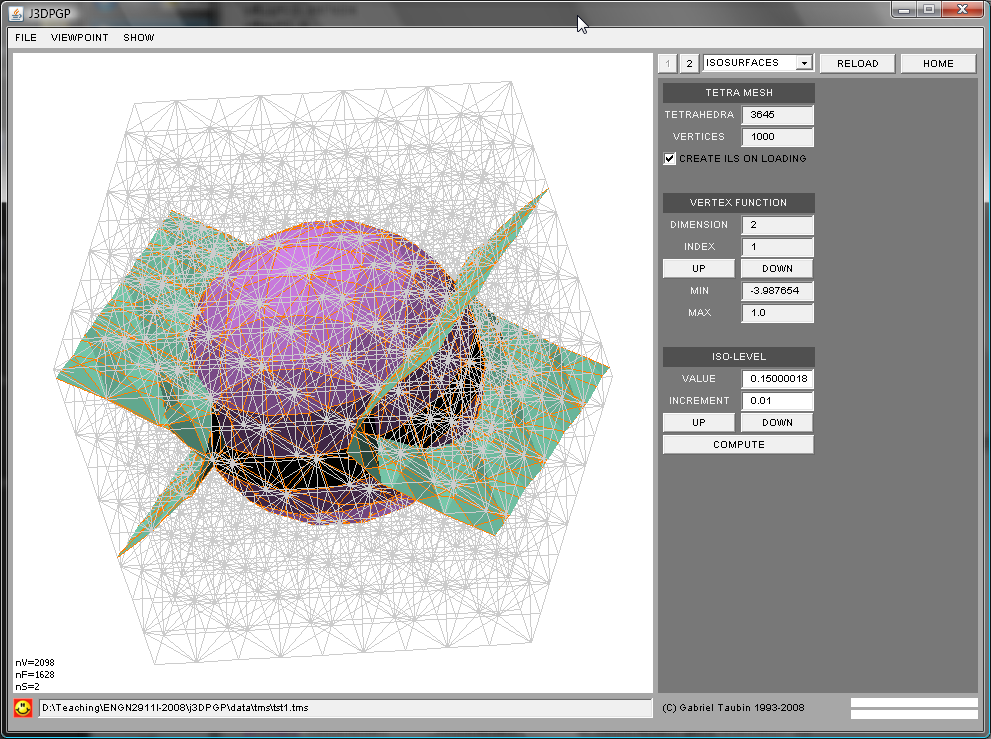
1.1 Extracting an Iso-surface as a polygon mesh
You have to traverse the scene graph looking for WrlTetraMeshIsoSurface nodes. When the data is read from file the WrlIndexedfaceSet arrays are all empty. It is your job to fill the coord array with isosurface vertices, and the coordIndex array with the isosurface faces. Since a mapping from tetrahedral mesh edges to isosurface vertices is needed to create the isosurface faces, we need to strat by building an instance of the Graph class for the tetrahedral mesh. This is not built for you as in the WrlIndexedFaceSet class. Once you know how many vertices the tetrahedral mesh has, you can create an empty graph, and then use the getEdge(i,j) and insertedge(i,j) Graph functions to create all the edges while you traverse the tetrahedra array. After that, the creation of isosurface vertices can be done in exactly the same way as for the isocurves. The faces can be created during a subsequent pass through the tetrahedra. The connectivity should be precomputed and stored in a table of length 16 (16=2^4 : number of cases based on implicit funtion signs at vertices). Since the number and type of polygons change from case to case, you have to figure out what data structure should be used for this table. Each tetrahedron cut by the isosurface produces either one triangle or one quadrilateral (which can be split into two triangles). Make sure that the output mesh is properly oriented. This can always be done directly from the connectivity (assuming the tetrahedral mesh is properly oriented).
1.2 Extracting an Iso-surface as a point cloud [extra credit]
This is actually simpler. Instead of creating isosurface faces by filling the coordIndex array of the WrlIndexedFaceSet, you have to assign one surface normal to each isosurface vertex, and store the resulting unit-length vectors in the normal array of the WrlIndexedFaceSet. Remember to set the normalPerVertex field to TRUE, and to leave the normalIndex array empty. You can compute these normals by combining the values of the implicit function in all the tetrahedra incident to the the edge containing the isosurface vertex. One way to compute polygon mesh normals per vertex is by averaging the incident face normals weighted by their corresponding surface areas. After the isosurface vertices have been created, you can compute these weights and surface normals during a pass over the tetrahedra, and accumulate them on arrays indexed by isosurface vertices. At the end of this traversal the averages can be computed, normalized to unit length, and store in the normal array of the WrlIndexedFaceSet.
1.3 Boolean combination [extra credit]
If two implicit functions f1 and f2, with corresponding isolevels l1 and l2, are given, the intersection of the two solids {p:f1(p)<=l1} and {p:f2(p)<=l2} is a solid volume whose boundary is a surface with normal discontinuities. Can you think of an algorithm to extract these "boolean isosurfaces" where the curves along which the normal vectors are discontinuous are explicitly represented as edges of the output polygon mesh?
Submission Instructions
You should submit clear evidence that you have successfully implemented as many features as possible. In particular, you should submit: (1) an archive named j3DPGP-HW2-Lastname.zip containing the modified source code, (2) a typeset document similar to this assignment handout documenting your implementations, and (3) provide modified meshes as WRL files demonstrating the algorithm output. In particular, please include modified meshes showing cutting and deletion, and describe in your write-up what modifications were performed. Final solutions should be emailed to the Instructor at taubin@brown.edu.
As for assignment 1, the best submissions will be asked to present a short demo in class and answer student questions regarding their solution.