Assignment 1:
Software Setup and Laser Line Detection
Instructor: Gabriel Taubin
Assignment developed by:
Daniel Moreno (2016) and
Peter Walecki (2018)
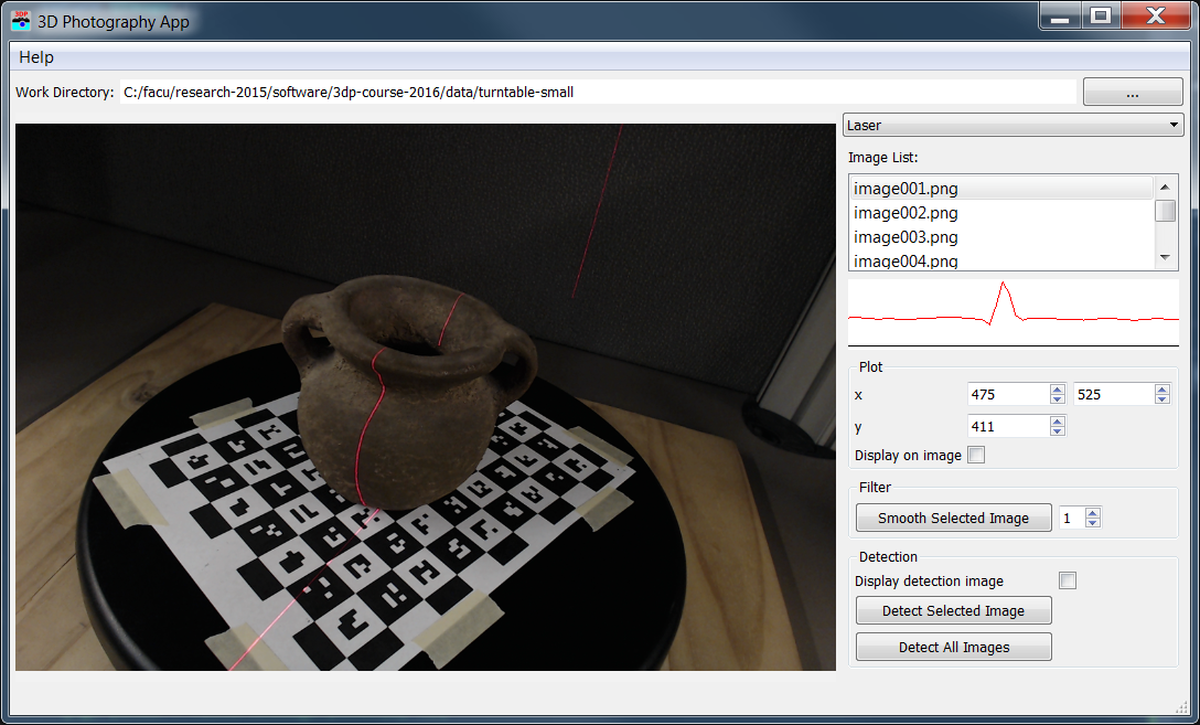
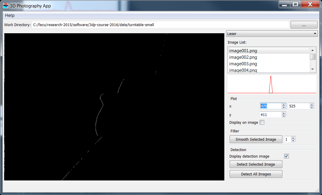
Figure 1: 3D Photography software displaying an input image (left) and the same image after laser line detection (right). Click images to zoom in.
Downloads:
3DP2018-A1.zip,
data-turntable-small.zip
laserlines-light.zip
laserlines-dark.zip
Introduction
The goal of this assignment is to setup the 3D Photography software which we will use in all the course assignments. In addition, we will implement a simple image filter operation and an image processing function to detect a laser line in images. This is the first step towards the implementation of our own laser slit 3D scanner that we will build during the course.
The software is written in C++ using Qt opensource framework and runs in multiple platforms. We also use Cmake build system to simplify the creation of the project in multiple operating systems. Your first task is to setup the build system in your own machine so that you can compile and run the 3D Photography software. You must install a compiler, such as Microsoft Visual Studio in a Windows environment, or Xcode in a MacOS environment. You must also install Qt 5.10, and Cmake 3.10 (install the latest stable version of both). We provide step-by-step directions for doing so in Microsoft Windows and Apple OS X operating systems. For help with other platforms contact the TA.
Setup build environment on Microsot Windows
Setup build environment on Apple OS X
1 Software
Once you have setup up your build environment you can begin working on the algorithms. You must download the source code and uncompress it on some work directory (e.g. 3dp). The directory structure will look like this:
 3DP2018
   |
   +--- assets
   +--- forms
   +--- src
         |
         +-- app
         +-- img
         +-- cam
         +-- homework: homework1.hpp, homework1.cpp
The code is organized so that 'assets' contains resource files (images, icons, shaders, ...), 'forms' has Qt form files, and the source code is in 'src': 'src/app' is the application, 'src/img' and 'src/cam' have support code for working with images and cameras, and 'homework' will have the files for each assignment. In this assignment you have to write your code in the file 'homework1.cpp', but you are free to modify as much of the software as you need. The functions you are about to implement corresponds to the 'Laser' panel in the software:

Download the sample to test your algorithms: data-turntable-small.zip, laserlines-light.zip, and laserlines-dark.zip.
2 Image filtering
You first coding task is to write the following function,
QImage filterImage(QImage const& inputImage, QVector filter);
which convolves 'inputImage' with the filter coefficients in the 'filter', and returns the filtered image as result. The original 'inputImage' remains unchanged. The given filter coefficients correspond to a separable filter and must be applied twice: first to convolve columns; and second to convolve rows. The filter is commonly given unnormalized and must be normalized. A sample code to use this function is:
    Qimage inputImage;
    QVector filter(QVector() << 1 << 4 << 6 << 4 << 1);
    QImage outImage = hw1::filterImage(inputImage, filter);
In the example, filter image will convolve first the columns and then the rows with the kernel \([1, 4, 6, 4, 1]\). The convolution operation is represented with '\(\ast\)'.
$$\text{outputImage} = \frac{1}{256}\ (\text{inputImage}\ \ast\ [1\ 4\ 6\ 4\ 1]) \ast \begin{bmatrix}1\\4\\6\\4\\1\end{bmatrix} $$Images are stored with the class QImage. Individual pixels can be accessed with the functions pixel and setPixel. The macros 'qRed', 'qGreen', and 'qBlue' may be used to access individual color components, and the macro 'qRgb(r,g,b)' to create a pixel element. Example:
    Qimage image;
    int rows = image.height();
    int cols = image.width();
    auto p = image.pixel(x, y);
    int r = qRed(p);
    int g = qGreen(p);
    int b = qBlue(p);
    image.setPixel(x, y, qRgb(r,g,b));
The function 'filterImage' is executed from the laser panel by clicking the button 'Smooth Selected Image'. The result is visualized as a result image and in the row intensity plot in the Laser Panel.
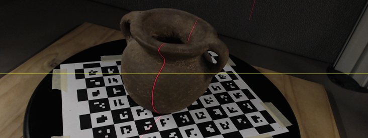
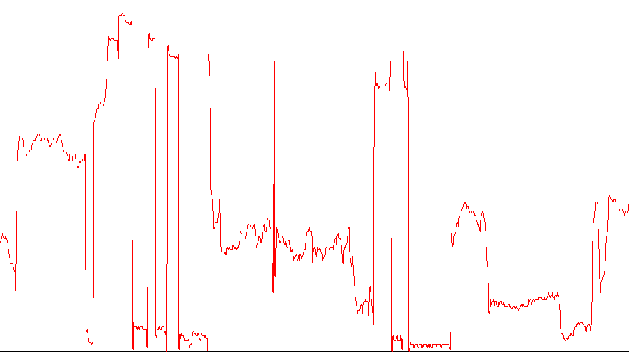
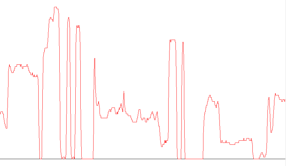
Figure 2: Input image (top), intensity plot at the yellow row on the original image (bottom left), plot result after the filter operation (bottom right).
3 Laser line detection
Your task is to write the code for laser detection in the function
QImage detectLaser(QImage const& inputImage);
The function 'detectLaser' takes an RGB image as input and creates a new image with all pixels set to 0, except the ones corresponding to the projected laser line, which must be set to 255. It is assumed that the laser is approximately a vertical red line on the image. The function scans the image row-by-row and for each row it sets all the pixels to 0 (black) except the one corresponding to the center of the detected laser line, which is set to 255 (white) if a laser line is detected.
You are free to write the algorithm as you prefer, any implementation generating the described output is correct. The TA implemented this function with the following steps:
- Smooth the input image to remove noise with the function 'filterImage' from the previous section.
- Isolate the red color by comparing the color channels as: v = r - (g+b)/2, v will have a high value for red pixels.
- Search the average maximum value of rows: avgMax = (max(row[0]) + max(row[1]) + ... + max(row(N)))/N
- Apply a threshold to all values much lower than the average maximum: e.g. if (pixel<0.8*avgMax) pixel = 0;
- Search the maximum of each row and set that pixel equal to 255

Figure 3: Output result image of applying the described algorithm to image ''image005.png' from the sample data.
The detection function is called from the software by clicking the 'Detect Selected Image' or 'Detect All Images' buttons.
Submission Instructions
You must upload a zip file of the complete application, including your implementation of the required functions, in canvas. If you need to communicate with the TA some implementation details, issues, exceptional results, extra work done, or anything else that you want to be considered while grading, do it so by writing a comment in the 'homework1.cpp' file, or add a document in the root folder of the software.
You must also include a folder called 'results' with images 001 to 005 of the decoded images of the sample data. The 3D photography software creates these images in a folder named 'detection' inside the folder with the original images.
References
- G. Taubin and D. Moreno. Build Your Own Desktop 3D Scanner. SIGGRAPH2014
- Lecture Notes: The Mathematics of Optical Triangulation
- Lecture Notes: The Laser Slit 3D Scanner