Introduction to Optical Triangulation
3D Printing has become a popular subject these days. More and more low cost desktop 3D printers are introduced, and open source projects let hobbyists build their own. Without models, a 3D printer is not really useful. Professionals have access to complete CAD software or modelers that costs thousands and need extensive training. They can also acquire a scene/object using 3D scanners. This course addresses the problem of creating 3D models for 3D printing by copying and modifying existing objects. As is the case for desktop 3D printers this course teaches the mathematical foundations of the various methods used to build 3D scanners, and includes specific instructions to build several low-cost homemade 3D scanners which can produce models of equal or better quality as many commercial products currently in the market.
These course notes are organized into three primary sections, spanning theoretical concepts, practical construction details, and algorithms for constructing high-quality 3D models. Chapters Introduction and Mathematics of Triangulation survey the field and present the unifying concept of triangulation. Chapters Camera and Projector Calibration, The Laser Slit Scanner, and Structured Light document the construction of projector-camera systems, slit-based 3D scanners, and 3D scanners based on structured lighting. The post-processing processes for generating polygon meshes from point clouds are covered in Chapter Points.
3D Scanning Technology
Metrology is an ancient and diverse field, bridging the gap between mathematics and engineering. Efforts at measurement standardization were first undertaken by the Indus Valley Civilization as early as 2600--1900 BCE. Even with only crude units, such as the length of human appendages, the development of geometry revolutionized the ability to measure distance accurately. Around 240 BCE, Eratosthenes estimated the circumference of the Earth from knowledge of the elevation angle of the Sun during the summer solstice in Alexandria and Syene. Mathematics and standardization efforts continued to mature through the Renaissance (1300--1600 CE) and into the Scientific Revolution (1550--1700 CE). However, it was the Industrial Revolution (1750--1850 CE) which drove metrology to the forefront. As automatized methods of mass production became commonplace, advanced measurement technologies ensured interchangeable parts were just that--accurate copies of the original.
Through these historical developments, measurement tools varied with mathematical knowledge and practical needs. Early methods required direct contact with a surface (e.g., callipers and rulers). The pantograph, invented in 1603 by Christoph Scheiner, uses a special mechanical linkage so movement of a stylus (in contact with the surface) can be precisely duplicated by a drawing pen. The modern coordinate measuring machine (CMM) functions in much the same manner, recording the displacement of a probe tip as it slides across a solid surface (see Figure 1.1). While effective, such contact-based methods can harm fragile objects and require long periods of time to build an accurate 3D model. Non-contact scanners address these limitations by observing, and possibly controlling, the interaction of light with the object.
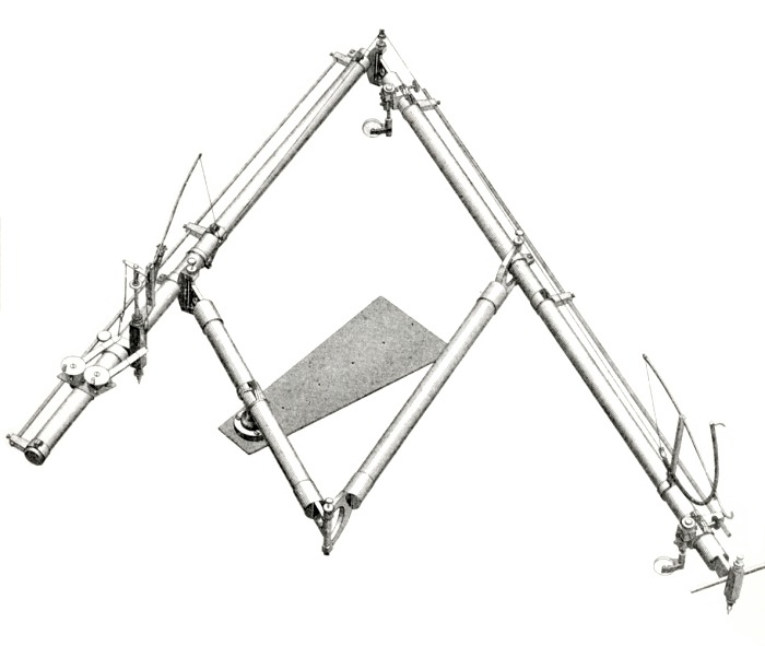
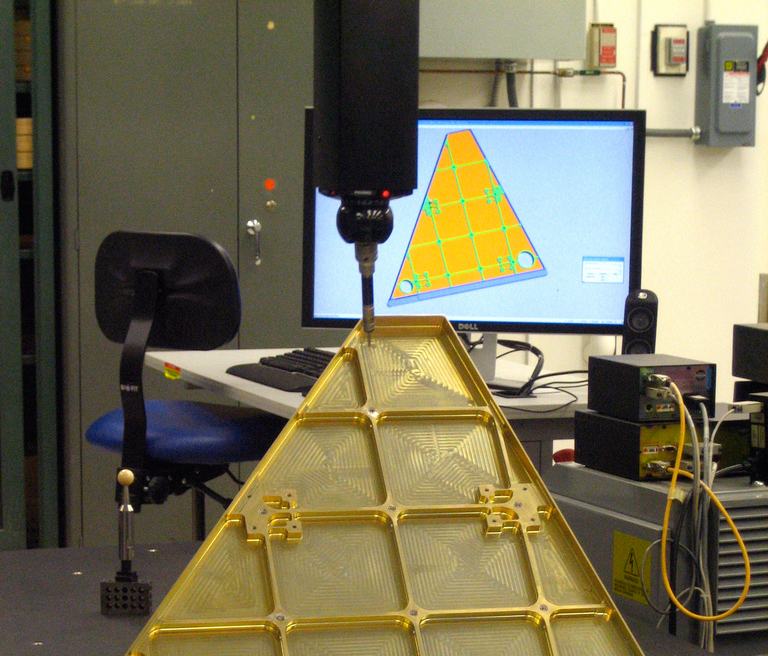
Figure 1.1
Contact-based shape measurement. (Left) A sketch of Sorenson's
engraving pantograph patented in 1867. (Right) A modern coordinate
measuring machining (from Flickr user hyperbolation). In both
devices, deflection of a probe tip is used to estimate object shape,
either for transferring engravings or for recovering 3D models,
respectively.
Passive Methods
Non-contact optical scanners can be categorized by the degree to which
controlled illumination is required. Passive scanners do not require
direct control of any illumination source, instead relying entirely on
ambient light. Stereoscopic imaging is one of the most widely used
passive 3D imaging systems, both in biology and engineering. Mirroring
the human visual system, stereoscopy estimates the position of a 3D
scene point by triangulation
[LN04];
first, the 2D projection of a given point is identified in each
camera. Using known calibration objects, the imaging properties of
each camera are estimated, ultimately allowing a single 3D line to be
drawn from each camera's center of projection through the 3D
point. The intersection of these two lines is then used to recover the
depth of the point.
Trinocular
[VF92]
and multi-view stereo
[HZ04]
systems have been introduced to improve the accuracy and reliability
of conventional stereoscopic systems. However, all such passive
triangulation methods require \emph{correspondences} to be found among
the various viewpoints. Even for stereo vision, the development of
matching algorithms remains an open and challenging problem in the
field
[SCD\∗06].
Today, real-time stereoscopic and multi-view systems are emerging,
however certain challenges continue to limit their widespread adoption
[MPL04].
Foremost, flat or periodic textures prevent robust matching. While
machine learning methods and prior knowledge are being advanced to
solve such problems, multi-view 3D scanning remains somewhat outside
the domain of hobbyists primarily concerned with accurate, reliable 3D
measurement.
Many alternative passive methods have been proposed to sidestep the
correspondence problem, often times relying on more robust computer
vision algorithms. Under controlled conditions, such as a known or
constant background, the external boundaries of foreground objects can
be reliably identified. As a result, numerous shape-from-silhouette
algorithms have emerged. Laurentini
[Lau94]
considers the case of a finite number of cameras observing a
scene. The visual hull is defined as the union of the generalized
viewing cones defined by each camera's center of projection and the
detected silhouette boundaries. Recently, free-viewpoint video
[CTMS03]
systems have applied this algorithm to allow dynamic adjustment of
viewpoint
[MBR\∗00][SH03]. Cipolla
and Giblin
[CG00]
consider a differential formulation of the problem, reconstructing
depth by observing the visual motion of occluding contours (such as
silhouettes) as a camera is perturbed.
Optical imaging systems require a sufficiently large aperture so that
enough light is gathered during the available exposure
time
[Hec01]. Correspondingly,
the captured imagery will demonstrate a limited depth of field; only
objects close to the plane of focus will appear in sharp contrast,
with distant objects blurred together. This effect can be exploited to
recover depth, by increasing the aperture diameter to further reduce
the depth of field. Nayar and Nakagawa
[NN94]
estimate shape-from-focus, collecting a focal stack by translating a
single element (either the lens, sensor, or object). A focus measure
operator
[Wik]
is then used to identify the plane of best focus, and its
corresponding distance from the camera.
Other passive imaging systems further exploit the depth of field by
modifying the shape of the aperture. Such modifications are performed
so that the point spread function (PSF) becomes invertible and
strongly depth-dependent. Levin et al.
[LFDF07]
and Farid
[Far97]
use such coded apertures to estimate intensity and depth from
defocused images. Greengard et al.
[GSP06]
modify the aperture to produce a PSF whose rotation is a function of
scene depth. In a similar vein, shadow moir\'{e} is produced by
placing a high-frequency grating between the scene and the camera. The
resulting interference patterns exhibit a series of depth-dependent
fringes.
While the preceding discussion focused on optical modifications for 3D
reconstruction from 2D images, numerous model-based approaches have
also emerged. When shape is known \emph{a priori}, then coarse image
measurements can be used to infer object translation, rotation, and
deformation. Such methods have been applied to human motion
tracking
[KM00][OSS\∗00][dAST\∗08],
vehicle recognition
[Sul95]
[FWM98],
and human-computer interaction
[RWLB01].
Additionally, user-assisted model construction has been demonstrated
using manual labeling of geometric primitives
[Deb97].
Active Methods
Active optical scanners overcome the correspondence problem using
controlled illumination. In comparison to non-contact and passive
methods, active illumination is often more sensitive to surface
material properties. Strongly reflective or translucent objects often
violate assumptions made by active optical scanners, requiring
additional measures to acquire such problematic subjects. For a
detailed history of active methods, we refer the reader to the survey
article by Blais
[Bla04]. In
this section we discuss some key milestones along the way to the
scanners we consider in this course.
Many active systems attempt to solve the correspondence problem by replacing one of the cameras, in a passive stereoscopic system, with a controllable illumination source. During the 1970s, single-point laser scanning emerged. In this scheme, a series of fixed and rotating mirrors are used to raster scan a single laser spot across a surface. A digital camera records the motion of this ``flying spot''. The 2D projection of the spot defines, with appropriate calibration knowledge, a line connecting the spot and the camera's center of projection. The depth is recovered by intersecting this line with the line passing from the laser source to the spot, given by the known deflection of the mirrors. As a result, such single-point scanners can be seen as the optical equivalent of coordinate measuring machines.
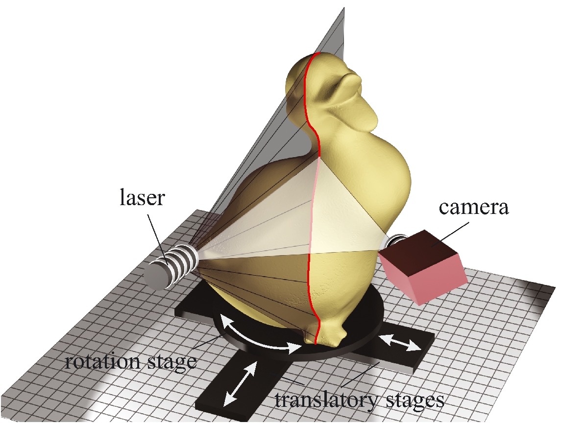
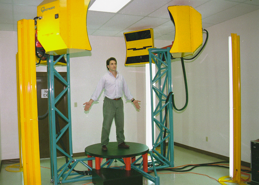 Figure 1.2
Active methods for 3D scanning. (Left) Conceptual diagram of a 3D
slit scanner, consisting of a mechanically translated laser
stripe. (Right) A Cyberware scanner, applying laser striping for
whole body scanning (from Flickr user NIOSH).
Figure 1.2
Active methods for 3D scanning. (Left) Conceptual diagram of a 3D
slit scanner, consisting of a mechanically translated laser
stripe. (Right) A Cyberware scanner, applying laser striping for
whole body scanning (from Flickr user NIOSH).
As with CMMs, single-point scanning is a painstakingly slow process. With the development of low-cost, high-quality CCD arrays in the 1980s, slit scanners emerged as a powerful alternative. In this design, a laser projector creates a single planar sheet of light. This ``slit'' is then mechanically-swept across the surface. As before, the known deflection of the laser source defines a 3D plane. The depth is recovered by the intersection of this plane with the set of lines passing through the 3D stripe on the surface and the camera's center of projection.
Effectively removing one dimension of the raster scan, slit scanners
remain a popular solution for rapid shape acquisition. A variety of
commercial products use swept-plane laser scanning, including the
Polhemus FastSCAN
[Pol],
the NextEngine
[Nex],
the SLP 3D laser scanning probes from Laser Design
[Las],
and the HandyScan line of products
[Cre]. While
effective, slit scanners remain difficult to use if moving objects are
present in the scene. In addition, because of the necessary separation
between the light source and camera, certain occluded regions cannot
be reconstructed. This limitation, while shared by many 3D scanners,
requires multiple scans to be merged---further increasing the data
acquisition time.
A digital [SPB04].
Both slit scanners and structured lighting are ill-suited for scanning dynamic scenes. In addition, due to separation of the light source and camera, certain occluded regions will not be recovered. In contrast, time-of-flight rangefinders estimate the distance to a surface from a single center of projection. These devices exploit the finite speed of light. A single pulse of light is emitted. The elapsed time, between emitting and receiving a pulse, is used to recover the object distance (since the speed of light is known). Several economical time-of-flight depth cameras are now commercially available . However, the depth resolution and accuracy of such systems (for static scenes) remain below that of slit scanners and structured lighting.
Active imaging is a broad field; a wide variety of additional schemes
have been proposed, typically trading system complexity for shape
accuracy. As with model-based approaches in passive imaging, several
active systems achieve robust reconstruction by making certain
simplifying assumptions about the topological and optical properties
of the surface. Woodham
[Woo89]
introduces photometric stereo, allowing smooth surfaces to be
recovered by observing their shading under at least three (spatially
disparate) point light sources. Hern\'andez et al.
[HVB∗07]
further demonstrate a real-time photometric stereo system using three
colored light sources. Similarly, the complex digital projector
required for structured lighting can be replaced by one or more
printed gratings placed next to the projector and camera. Like shadow
moir\'{e}, such projection moir\'{e} systems create depth-dependent
fringes. However, certain ambiguities remain in the reconstruction
unless the surface is assumed to be smooth.
% survey of publication venues Active and passive 3D scanning methods continue to evolve, with recent progress reported annually at various computer graphics and vision conferences, including 3-D Digital Imaging and Modeling (3DIM), SIGGRAPH, Eurographics, CVPR, ECCV, and ICCV. Similar advances are also published in the applied optics communities, typically through various SPIE and OSA journals.
3D Scanners Studied in this Course
This course is grounded in the unifying concept of triangulation. At their core, stereoscopic imaging, slit scanning, and structured lighting all attempt to recover the shape of 3D objects in the same manner. First, the correspondence problem is solved, either by a passive matching algorithm or by an active ``space-labeling'' approach (e.g., projecting known lines, planes, or other patterns). After establishing correspondences across two or more views (e.g., between a pair of cameras or a single projector-camera pair), triangulation recovers the scene depth. In stereoscopic and multi-view systems, a point is reconstructed by intersecting two or more corresponding lines. In slit scanning and structured lighting systems, a point is recovered by intersecting corresponding lines and planes.
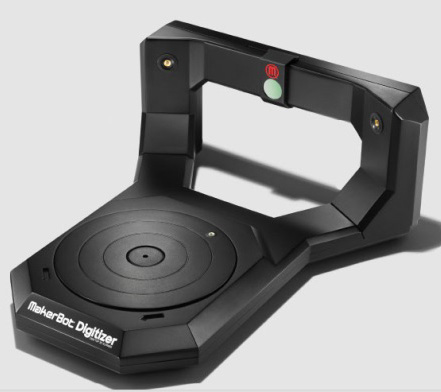
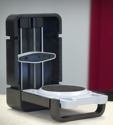
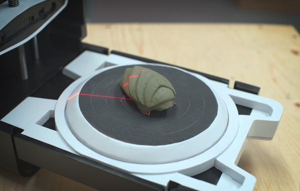
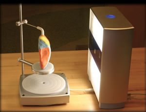
Figure 1.3Desktop 3D Scanners based on Laser Plane
Triangulation. From left to right: MakerBot Digitizer, Matterform
Photon, and NextEngine 3D Scanner HD.
To elucidate the principles of such triangulation-based scanners, this course describes how to construct a classic turntable-based slit scanner, and a structured lighting system. The course also covers methods to register and merge multiple scans, to reconstruct polygon mesh surfaces from multi-scan registered point clouds, and to optimize the reconstructed meshes for various purposes. In all 3D scanner designs, the methods used to calibrate the systems are integral part of the design, since they have to be carefully constructed to produce accurate and precise results.
We first study the slit scanner, where a laser line projector iluminates an abject, and a camera captures an image of some or all the illuminated object points. Figure 1.3 shows some commercial desktop 3D scanners based on this method. Image processing techniques are used to detect the pixels corresponding to illuminated points visible by the camera. Ray-plane triangulation equations are used to reconstruct 3D points belonging to the intersection of the plane of laser light and the object. To recover denser sets of 3D points, the laser projector has to be moved while the camera remains static with respect to the object, and the process has to be repeated until a satisfactory number of points has been reconstructed. Alternatively, the object is placed on a linear stage or a turntable, the laser projector is kept static with respect to the camera. The linear stage or turntable is iteratively moved to a new position where an image is captured by the camera. As in the first case, a large number of images must be captured to generate a dense point cloud. In both cases tracking and estimating the motion with precision is required. Computer-controlled motorized linear stages or turntables are normally used for this purpoose. In Chapter The Laser Slit Scanner we describe how to build a low cost turntable-based slit scanner.
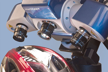
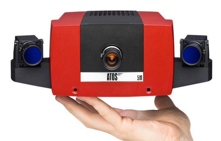
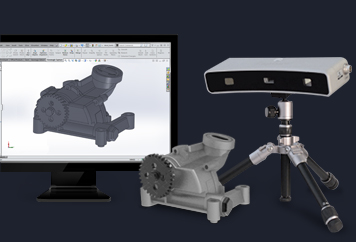
Figure 1.4
Industrial 3D Scanners based on Structured Lighting. From left to
right: Breuckmann SmartScan, ATOS CompactScan, and Geomagic
Capture.
Since slit-based scanning systems are line scan systems, they require capturing and processing large numbers of images to produce dense area scans. Structured lighting systems can be used to significantly reduce the number of images (typically by two or more orders of magnitude) required to generate dense 3D scans. Figure 1.4 show some examples of commercial 3D scanners based on structured lighting. In Chapter Structured Light we describe how to build a low cost structured lighting system using a single LED pico-projector and one or more digital cameras. Many good HD USB web-cameras exist today which can be used for this purpose, but many other options exist today ranging from high end DSLRs to smartphone cameras.
By providing example data sets, open source software, and detailed implementation notes, we hope to enable beginners and hobbyists to replicate our results. We believe the process of building your own 3D scanner to complement your 3D printer will be enjoyable and instructive. Along the way, you'll likely learn a great deal about the practical use of projector-camera systems, hopefully in a manner that supports your own research.