3D Scanning with Structured Light
In this chapter we describe how to build a structured light scanner using one or more digital cameras and a single projector. While the Laser Slit 3D Scanner implemented in the previous chapter is widely used, it needs hundreds of images to build a complete model with acceptable detail. It could be argued that the scanning process is inefficient, in the sense that only a very small set of pixels illuminated by the laser contribute to the scan in each image, and the rest are mostly ignored. On the contrary, a Structured Light Scanner replaces the projected laser line with a data projector capable of displaying \(2\)-dimensional patterns covering a much larger object region, and generating a 3D model containing all the points being simultaneously illuminated by the projector and visible from the cameras. More information is extracted from each image, thus, reducing the number of images required and the total scanning time. A turntable is still useful, but only a few rotations will be required to build a full model.
The structured light scanner builds on top of the theory and algorithms developed in the previous chapters. Reconstruction is now accomplished using ray-ray triangulation between projector and camera pixels. The key concept here is that correspondences are established by decoding certain structured light sequences. The methods described below are already implemented in the Projector-Camera Calibration software introduced in Chapter Camera and Projector Calibration. Here we will expand on how projector columns and rows are coded in the patterns and later decoded from the camera images.
Structured Light Scanner
Structured light scanners became highly popular in the recent years, mainly because of the low cost and wide availability of quality data projectors and cameras. The concept of structured light refers to the idea of the scene being illuminated by specially designed patterns. A quick review of the literature will reveal that many different patterns have been proposed using different coding strategies. Salvi et al. [SFPL10] give several pattern classifications depending on whether they make use of color, the number of images required, the type of encoding, and whether they encode discrete or continuous quantities, a few examples are shown in Figure 5.1. We will focus only on discrete binary patterns and a minor variant known as Gray code, both are shown in Figures 5.3 and Figure 5.4.
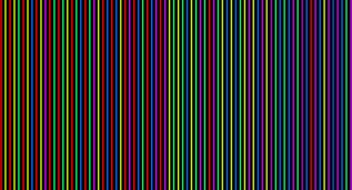
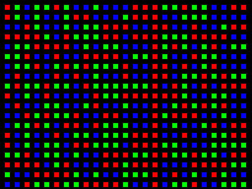
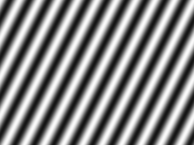
Figure 5.1 Patterns with different coding strategies. Left: De Bruijn color stripes; Center: Color M-Array; Right: Phase Shifting.
Scanner Hardware
Our scanner is built with a single camera and a single data projector. This choice replicates passive stereo scanners which observe a scene with a pair of cameras and build a 3D model by triangulating points visible in both of them. Identifying the exact position where points from the first view appear in the second view is a difficult task in general, known as establishing pixel correspondences. Here, we replace one camera by a projector to simplify this task. As with other systems, several cameras and projectors could be added to extend the scanned area, or to provide more accurate measurements, but we will not discuss those variants here, however, once understood the concepts from this chapter, it should be more or less straightforward to generalized them to other configurations.
We will use the Logitech C920 Webcam and an Optoma ML550 projector setup as in Figure 5.2. The target object may be placed on a turntable and several scans can be aligned to build a \(360^\circ\) model by calibrating the turntable as in Chapter The Laser Slit 3D Scanner. It is advisable to mount the camera and projector on a tripod because they must remain fixed at all times after they are calibrated.
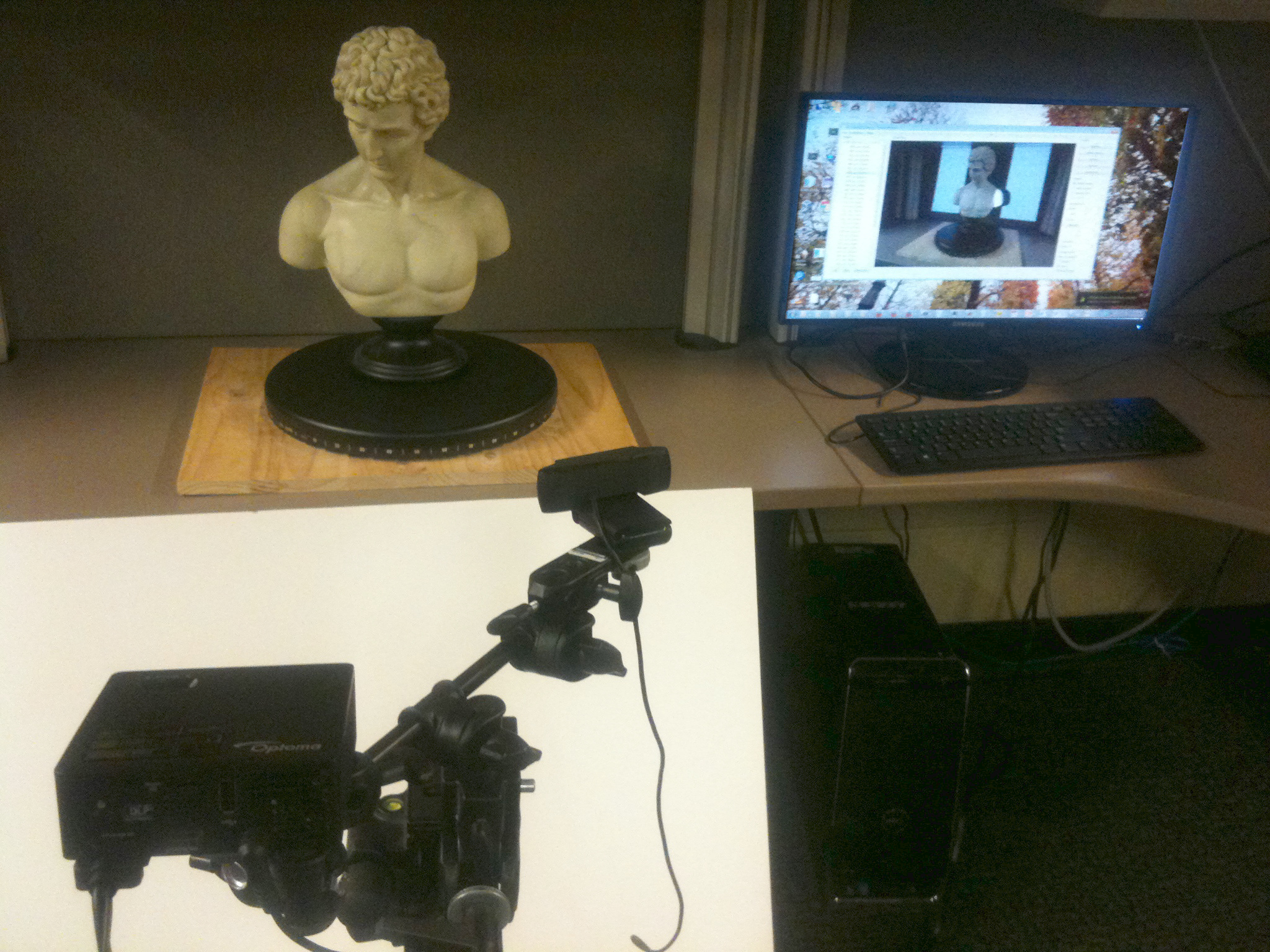
Figure 5.2 Structured light scanner sample setup: Optoma ML550 projector, Logitech C920 Webcam, target object on a turntable, and computer.
Structured Light Sequences
The primary benefit of introducing the projector is to eliminate the mechanical motion required in the Laser Slit 3D Scanner. Assuming minimal lens distortion, the projector can be used to display a single column (or row) of white pixels translating against a black background; thus, as many images as columns (or rows) in the projector would be required in order to assign the correspondences, in our implementation, between camera pixels and projector columns (or rows). After establishing the correspondences and calibrating the system, a 3D point cloud is reconstructed using familiar ray-plane triangulation. However, a simple strategy like this does not fully exploit the projector. Since we are free to project arbitrary 24-bit color images, one would expect there to exist a sequence of coded patterns, besides a simple translation of a single stripe, that allow the projector-camera correspondences to be assigned in relatively few frames. In general, the identity of each plane can be encoded spatially (i.e., within a single frame) or temporally (i.e., across multiple frames), or with a combination of both spatial and temporal encodings. There are benefits and drawbacks to each strategy. For instance, purely spatial encodings allow a single static pattern to be used for reconstruction, enabling dynamic scenes to be captured. Alternatively, purely temporal encodings are more likely to benefit from redundancy, reducing reconstruction artifacts.
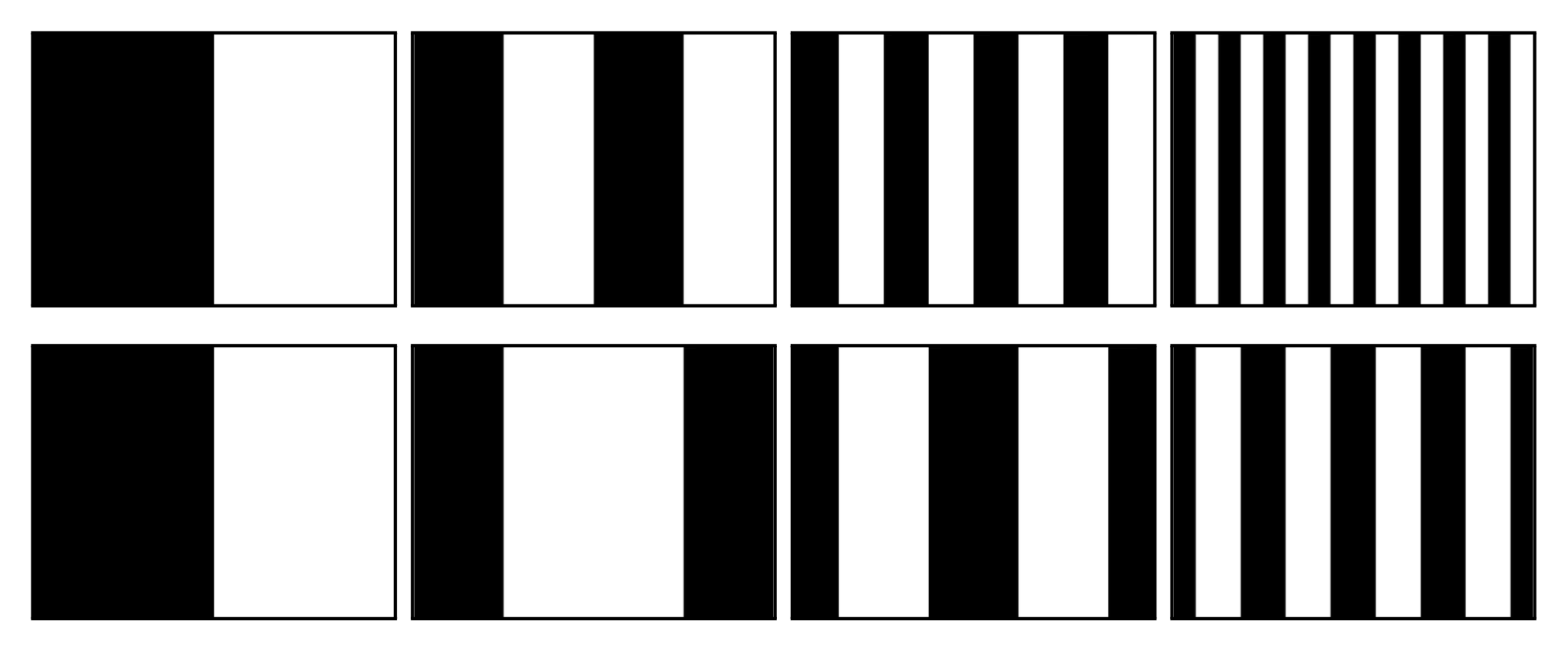
Figure 5.3 Structured light illumination sequences. (Top row, left to right) The first four bit planes of a binary encoding of the projector columns, ordered from most to least significant bit. (Bottom row, left to right) The first four bit planes of a Gray code sequence encoding the projector columns.
In this chapter we will focus on purely temporal encodings. While such patterns are not well-suited to scanning dynamic scenes, they have the benefit of being easy to decode and are robust to surface texture variation, producing accurate reconstructions for static objects (with the normal prohibition of transparent or other problematic materials). A simple binary structured light sequence was first proposed by Posdamer and Altschuler in 1981 [PA82]. As shown in Figure 5.3, the binary encoding consists of a sequence of binary images in which each frame is a single bit plane of the binary representation of the integer indices for the projector columns (or rows). For example, column 546 in our prototype has a binary representation of \(1000100010\) (ordered from the most to the least significant bit). Similarly, column 546 of the binary structured light sequence has an identical bit sequence, with each frame displaying the next bit.
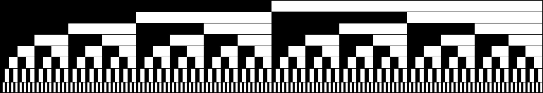
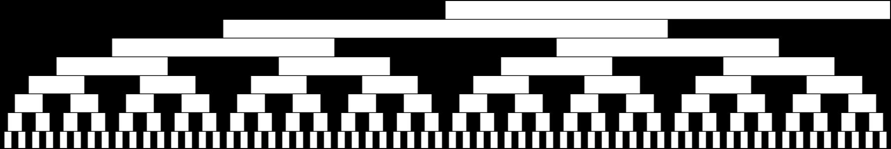
Figure 5.4 Comparison of binary (top) and Gray code (bottom) structured light sequences. Each image represents the sequence of bit planes displayed during data acquisition. Image rows correspond to the bit planes encoding the projector columns, assuming a projector resolution of \(1024\times 768\), ordered from most to least significant bit (from top to bottom).
Considering the projector-camera arrangement as a communication system, then a key question immediately arises; what binary sequence is most robust to the known properties of the channel noise process? At a basic level, we are concerned with assigning an accurate projector column/row to camera pixel correspondence, otherwise triangulation artifacts will lead to large reconstruction errors. Gray codes were first proposed as one alternative to the simple binary encoding by Inokuchi et al. in 1984 [ISM84]. The reflected binary code was introduced by Frank Gray in 1947 [GC]. As shown in Figure 5.4, the Gray code can be obtained by reflecting, in a specific manner, the individual bit-planes of the binary encoding. Pseudocode for converting between binary and Gray codes is provided in Table 5.1. For example, column 546 in our implementation has a Gray code representation of \(1100110011\), as given by the method Bin2Gray. The key property of the Gray code is that two neighboring code words (e.g., neighboring columns in the projected sequence) only differ by one bit (i.e., adjacent codes have a Hamming distance of one). As a result, the Gray code structured light sequence tends to be more robust to decoding errors than a simple binary encoding and binary codes should no be used in general.
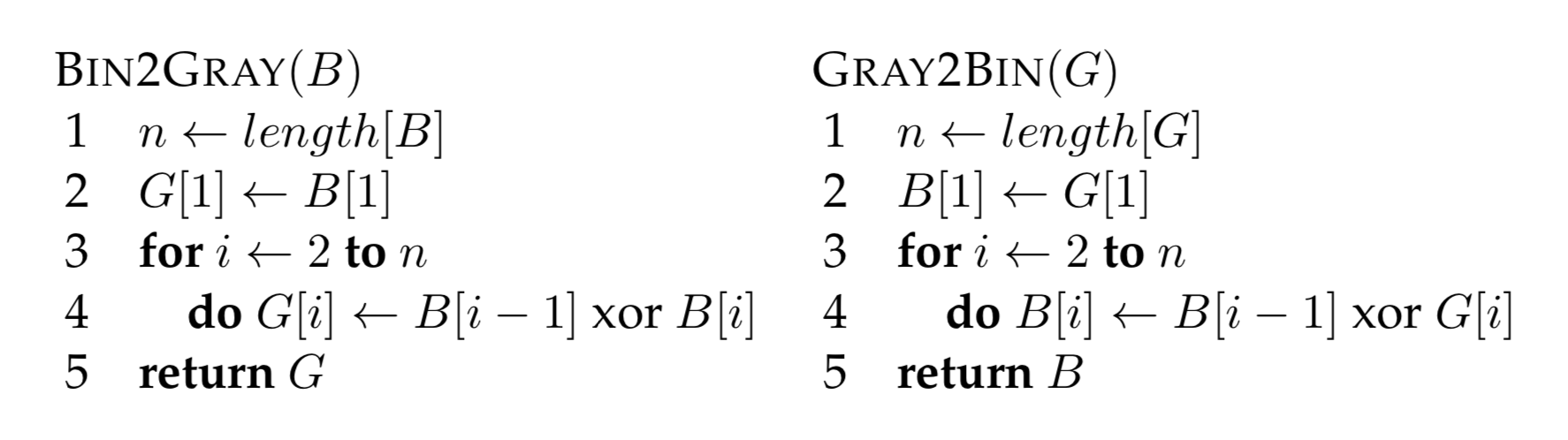
Table 5.1 {Pseudocode for converting between binary and Gray codes. (Left) Method Bin2Gray accepts an \(n\)-bit Boolean array, encoding a decimal integer, and returns the Gray code \(G\). (Right) Conversion from a Gray to a binary sequence is accomplished using the method Gray2Bin.}
Image Processing
The algorithms used to decode the structured light sequences described in the previous section are relatively straightforward. For each camera, it must be determined whether a given pixel is directly illuminated by the projector in each displayed image. If it is illuminated in any given frame, then the corresponding code bit is set high, otherwise it is set low. The decimal integer index of the corresponding projector column (and/or row) can then be recovered by decoding the received bit sequences for each camera pixel. A user-selected intensity threshold is used to determine whether a given pixel is illuminated. For instance, \(\lceil \log_2 w\rceil + 2\) images could be used to encode the projector columns, with the additional two images consisting of all-white and all-black frames. The average intensity of the all-white and all-black frames could be used to assign a per-pixel threshold; the individual bit planes of the projected sequence could then be decoded by comparing the received intensity to the threshold.
In practice, a single fixed threshold results in decoding artifacts. For instance, certain points on the surface may only receive indirect illumination scattered from directly-illuminated points. In certain circumstances the scattered light may cause a bit error, in which an unilluminated point appears illuminated due to scattered light. Depending on the specific structured light sequence, such bit errors may produce significant reconstruction errors in the 3D point cloud. One solution is to project each bit plane and its inverse. While \(2 \lceil \log_2 w\rceil\) frames are now required to encode the projector columns, the decoding process is less sensitive to scattered light, since a variable per-pixel threshold can be used. Specifically, a bit is determined to be high or low depending on whether a projected bit-plane or its inverse is brighter at a given pixel. Typical decoding results are shown in Figure 5.5.
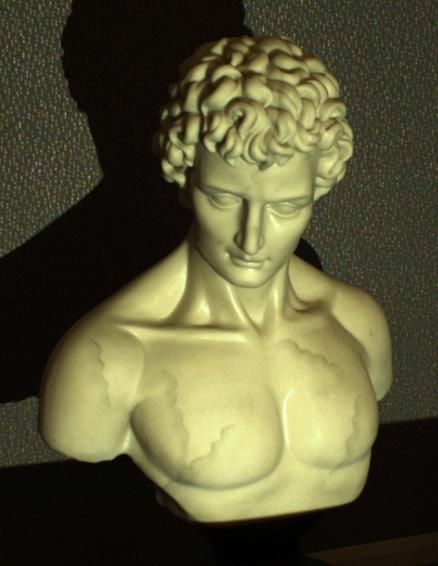
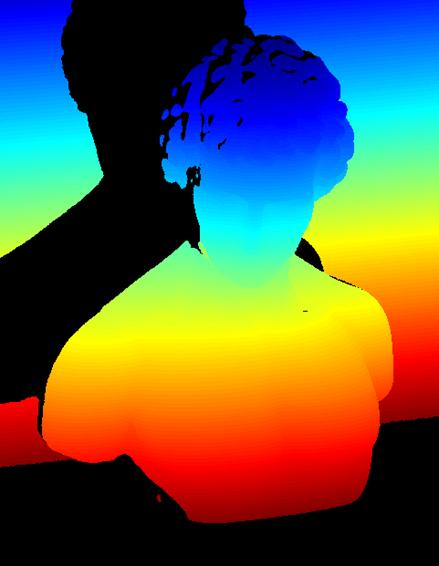
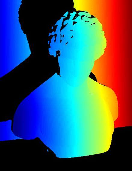
Figure 5.5 Decoding structured light illumination sequences. (Left) Camera image captured while projecting an all white frame. Note the shadow cast on the background plane, prohibiting reconstruction in this region. (Center) Typical decoding results for a Gray code structured light sequence, with projector row and camera pixel correspondences represented using a \texttt{jet} colormap in {\sc Matlab}. Points that cannot be assigned a correspondence with a high confidence are shown in black. (Right) Similar decoding results for projector column correspondences.
The Projector-Camera Calibration and Scanning software uses a Gray code sequence and its inverse, for both columns and rows, plus the all-white and all-black images, but it implements a method called Robust pixel classification [XA07] to decide if a pixel was white, black, or it is set as unknown if cannot be decided. Robust pixel classification provides a set of rules designed to take into account that indirect illumination may cause some pixels to appear brighter than they should be. The rules require to separate each image into global illumination and direct illumination components. We call direct illumination the light which hits the scene coming directly from the projector, and global illumination any other light contributions including the ambient light. Implementing the robust classification is optional but we have found that the result improves without adding much decoding overhead.
As with any communication system, the design of structured light sequences must account for anticipated artifacts introduced by the communication channel. In a typical projector-camera system decoding artifacts are introduced from a wide variety of sources, including projector or camera defocus, scattering of light from the surface, and temporal variation in the scene (e.g., varying ambient illumination or a moving object). We have provided a variety of data sets for testing your decoding algorithms. In particular, the \(\textsf{man}\) sequence has been captured using both binary and Gray code structured light sequences. Furthermore, both codes have been applied when the projector is focused and defocused at the average depth of the sculpture. We encourage the reader to study the decoding artifacts produced under these non-ideal, yet commonly encountered, circumstances.
Calibration
The structured light scanner uses the triangulation principle to reconstruct the scanned model. In order to map pixel positions to world rays the system must be calibrated. In our case, we need to find the intrinsic parameters of the camera and projector, and the relative rotation and translation between them. If a turntable is used, the world coordinate system must be placed at its center of rotation as in the previous chapter, which has to be calibrated, and the rotation and translation from world coordinates to camera coordinates must be found. Without a turntable, the world coordinate system may be placed at the camera (or projector) center and with the same orientation. We will use the Projector-Camera Calibration software to calibrate everything but the turntable, which must be calibrated as in Section The Laser Slit 3D Scanner; Calibration.
Reconstruction
The decoded set of camera and projector correspondences can be used to reconstruct a 3D point cloud. Several reconstruction schemes can be implemented using the sample sequences. The projector column correspondences can be used to reconstruct a point cloud using ray-plane triangulation. A second point cloud can be reconstructed using the projector row correspondences. Finally, the projector pixel to camera pixel correspondences can be used to reconstruct the point cloud using ray-ray triangulation (i.e., by finding the closest point to the optical rays defined by the projector and camera pixels). A simple per-point RGB color can be assigned by sampling the color of the all-white camera image for each 3D point. Reconstruction artifacts can be further reduced by comparing the reconstruction produced by each of these schemes. Typical results are shown in Figures 5.6 through 5.9.
The provided software implements ray-ray triangulation between camera and projector pixels, using the approximate intersection from Section The Mathematics of Optical Triangulation; Line-Line Intersection. In order to remove errors, the minimum distance between rays is also computed and compared with a user-set threshold, a small distance is considered as intersection and a 3D point is created, otherwise the point is ignored. As usual, if the dimensions of the scanning volume is available, or can be roughly estimated, only points within the volume must be added to the model.
f.jpg)
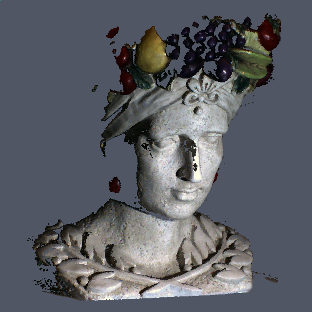
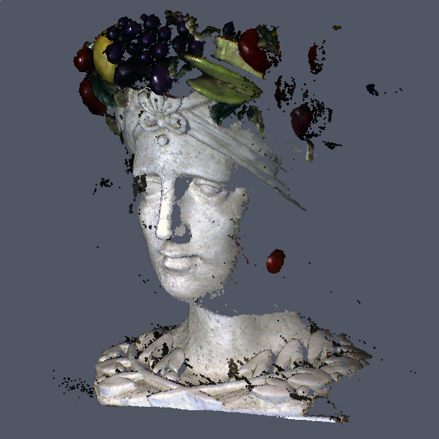
Figure 5.6 Reconstruction of the \(\textsf{chiquita}\) Gray code sequence.
.jpg)
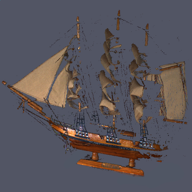
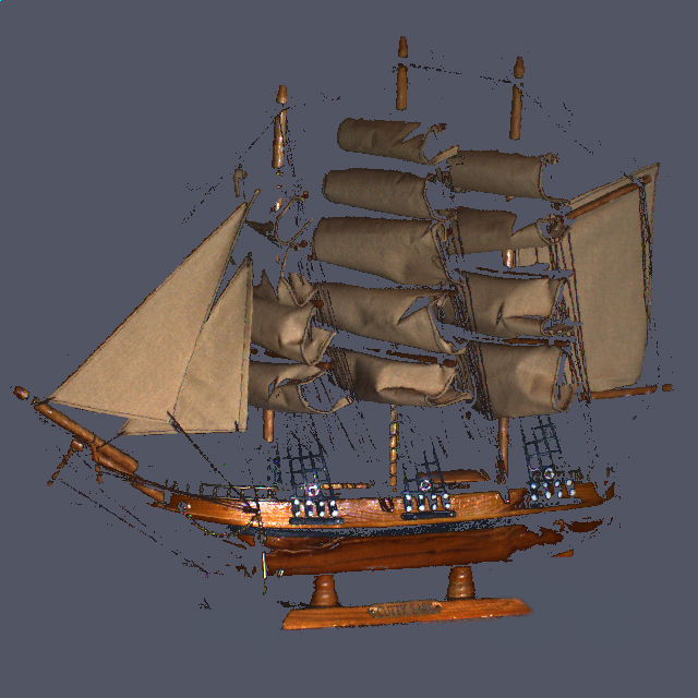
Figure 5.7 Reconstruction of the \(\textsf{schooner}\) Gray code sequence.
.jpg)
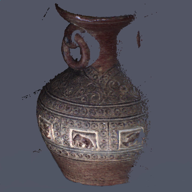
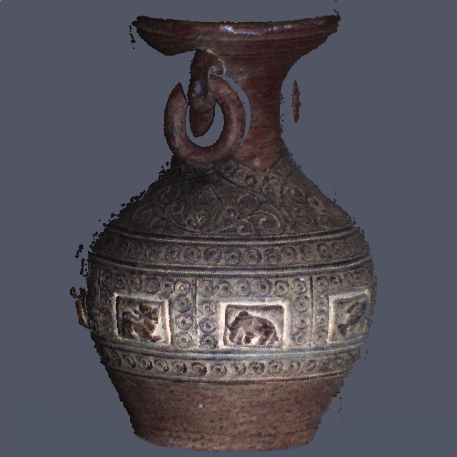
Figure 5.8 Reconstruction of the \(\textsf{urn}\) Gray code sequence.
.jpg)
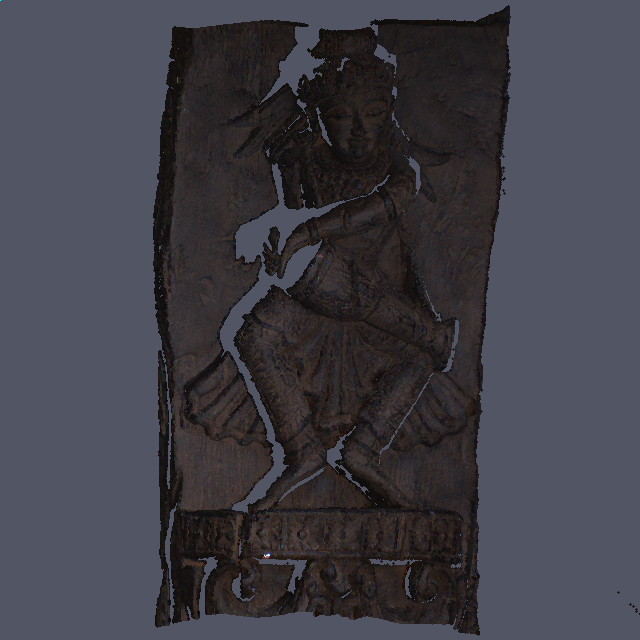
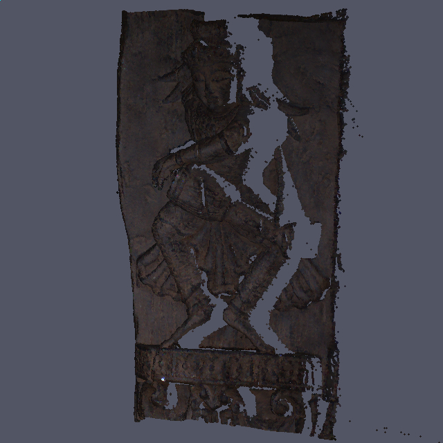
Figure 5.9 Reconstruction of the \(\textsf{drummer}\) Gray code sequence.
Sample software
The structured light scanner produces a colored 3D point cloud. Only points that are both imaged by a camera and illuminated by the projector can be reconstructed. As a result, a complete 3D model of an object would typically require merging multiple scans obtained by moving the scanning apparatus or object (e.g., by using a turntable). These issues are considered in Chapter Reconstructing Surfaces From Point Clouds. We encourage the reader to implement their own solution so that measurements from multiple cameras, projectors, and 3D point clouds can be merged. As a reference the Projector-Camera Calibration software described Chapter Camera and Projector Calibration implements both the calibration and scanning using a structured light system.
Data acquisition for scanning is identical as how the calibration sequences were collected. A reconstruction for each individual sequence is performed by highlighting the sequence folder name in the list on the left part of the main screen and clicking \(\textsf{Reconstruct}\). Once the reconstruction is complete a file save dialog will open asking a pointcloud file name. At the time of writing, the software does not include a visualization of the result but the generated file can be opened using a standard 3D viewer (e.g. Meshlab). The software can reconstruct as many scans of an object as required but it will not merge them into a single model, each reconstruction will be stored as a separate pointcloud and must be merged using a separate software. Optionally, the surface normal at each point is estimated and added to the output creating an oriented pointcloud instead. Normals are useful to create more interesting visualizations and they are usually required by surface reconstruction tools.